Line pipe are essential tools in the petroleum industry. They are of vital importance to the oil production process as well as to other operations that require the transport of gas or liquid.
As they have a variety of uses, they are manufactured in different sizes or dimensions. As a result of these differences, line pipe vary in areas like weight and thickness but are nonetheless made to be durable enough to withstand great amounts of pressure.
Thus, different specifications are made to identify these line pipe especially for the variety of clients that may need them. One of these specifications is the line pipe schedule.
Line Pipe Schedule
The line pipe schedule describes the thickness of the wall of the pipe as well as its inside diameter. Aside from describing the size of the tubing, the line pipe schedule can be used to classify the line pipe for different amounts of pressure (high or low) and for different amounts of temperature.
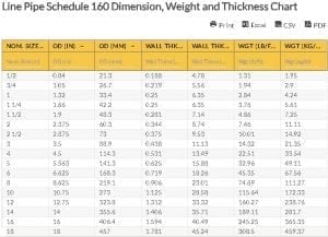
What is important to note is that as the number of the schedule increases, the wall thickness becomes greater. While the schedule number may be the same for different sizes of pipe, the actual wall thickness may be different. One of these line pipe schedule numbers is line pipe schedule 10 as seen on the Line Pipe Schedule 10 Dimension, Weight and Thickness Chart.
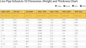
Line Pipe Schedule 10 Dimension, Weight and Thickness Chart
| Nom. Size (in) | OD (in) | OD (mm) | Wall Thkns (in) | Wall Thkns (mm) | Wgt (lb/ft) | Wgt (kg/m) | |
|---|---|---|---|---|---|---|---|
| wdt_ID | Nom. Size (in) | OD (in) | OD (mm) | Wall Thkns (in) | Wall Thkns (mm) | Wgt (lb/ft) | Wgt (kg/m) |
| 1 | 1/8 | 0.41 | 10.3 | 0.049 | 1.24 | 0.19 | 0.28 |
| 2 | 1/4 | 0.54 | 13.7 | 0.065 | 1.65 | 0.33 | 0.49 |
| 3 | 3/8 | 0.68 | 17.1 | 0.065 | 1.65 | 0.42 | 0.63 |
| 4 | 1/2 | 0.84 | 21.3 | 0.083 | 2.11 | 0.67 | 1 |
| 5 | 3/4 | 1.05 | 26.7 | 0.083 | 2.11 | 0.86 | 1.28 |
| 6 | 1 | 1.32 | 33.4 | 0.109 | 2.77 | 1.4 | 2.09 |
| 7 | 1 1/4 | 1.66 | 42.2 | 0.109 | 2.77 | 1.81 | 2.7 |
| 8 | 1 1/2 | 1.9 | 48.3 | 0.109 | 2.77 | 2.09 | 3.11 |
| 9 | 2 | 2.375 | 60.3 | 0.109 | 2.77 | 2.64 | 3.93 |
| 10 | 2 1/2 | 2.875 | 73 | 0.12 | 3.05 | 3.53 | 5.26 |
table.wpDataTable { table-layout: fixed !important; }
table.wpDataTable td.numdata { text-align: right !important; }
/* th background color */
.wpdt-c .wpDataTablesWrapper table.wpDataTable thead th,
.wpdt-c .wpDataTablesWrapper table.wpDataTable thead th.sorting {
background-color: #f7c54b !important;
background-image: none !important;
}
/* th border color */
.wpdt-c .wpDataTablesWrapper table.wpDataTable thead th,
.wpdt-c .wpDataTablesWrapper table.wpDataTable thead th.sorting {
border-color: #6b6b6b !important;
}
/* th font color */
.wpdt-c .wpDataTablesWrapper table.wpDataTable thead th {
color: #333333 !important;
}
.wpdt-c .wpDataTablesWrapper table.wpDataTable thead th.sorting:after,
.wpdt-c .wpDataTablesWrapper table.wpDataTable thead th.sorting_asc:after {
border-bottom-color: #333333 !important;
}
.wpdt-c .wpDataTablesWrapper table.wpDataTable thead th.sorting_desc:after {
border-top-color: #333333 !important;
}
/* th active/hover background color */
.wpdt-c .wpDataTablesWrapper table.wpDataTable thead th.sorting_asc,
.wpdt-c .wpDataTablesWrapper table.wpDataTable thead th.sorting_desc,
.wpdt-c .wpDataTablesWrapper table.wpDataTable thead th.sorting:hover {
background-color: #ebebeb !important;
background-image: none !important;
}
.wpdt-c .wpDataTablesWrapper table.wpDataTable thead tr:nth-child(2) th {
overflow: visible;
}
Line Pipe Schedule 10 Dimension, Weight and Thickness Chart Terms:
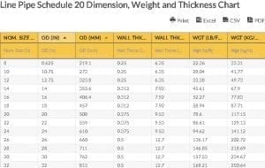
In the Line Pipe Schedule 10 Dimension, Weight and Thickness Chart, there are four key terms: 1. nominal size (in inches), 2. outside diameter (both in inches and millimeters), 3. wall thickness (both in inches and millimeters), and 4. weight (both in pounds per feet and kilograms per meter). The nominal size is used as the primary specification for the pipe, as its value is based on a set of non-specific standard sizes for line pipe.
Along with the ‘universal nominal size’, the outside diameter is used to specify the line pipe because it determines the overall dimensions and capacity of a line pipe. The two remaining terms on the Line Pipe Schedule 10 Dimension, Weight and Thickness Chart–the wall thickness and weight–are basically factors that depend on the nominal size and outside diameter that are specified to identify the strength of the line pipe.
Line Pipe Schedule 10 Dimension, Weight and Thickness Chart Abbreviations:
- OD – Outside Diameter
- in – inches
- mm – millimeter
- lb/ft – pounds per feet
- kg/m – kilogram per meter
- Wgt – Weight
- Nom. Size – Nominal Size
- Wall Thkns – Wall Thickness
Go here if you are looking for the Line Pipe Schedule 20 Dimension, Weight and Thickness Chart.
The Oilfield Equipment related post Line Pipe Schedule 10 Dimension, Weight and Thickness Chart is from Flowtech Energy. Looking for Oilfield Equipment including New, Used, Remanufactured and Surplus Oilfield Supply, check out our inventory or call our toll free number at 877-645-6693 for more information.
From https://www.flowtechenergy.com/charts/line-pipe-schedule-10-dimension-weight-and-thickness-chart/