Drill rod thread basically differs for every type of drill rod. Threads of standard drill rods come in aluminum or mid-weight steel, allowing ergonomic flexibility that provides better handling capacities even on most demanding applications. Other conditions, including mineral explorations, require rod threads that can be used with standard core barrels, just like the WJ type threads.
Drill rod thread undergoes evaluation during drill rod production and drill rod couplings to ensure that high-quality steel is used and that it can hold up against drilling under the most severe environments.
Drill Rod Thread Types
Parallel Threaded Rods
These rods have female threads at both ends of the steel tube, which can be replaced with pin-to-pin couplers. High-quality seamless carbon steel is used to produce these rods, ensuring sturdiness and uniformity. On the other hand, heat treated-alloy steel is utilized to manufacture male-threaded couplings, delivering maximum durability and wear endurance. Rotary drilling operations can best benefit from these rods.
Taper Threaded Rods
Both replaceable male and female tool joints are available with these drill rods; these are bolted into the rod tube. Heat-treated alloy steel is used to produce these rods to ensure utmost durability and wear resistance.
Drill Rod Thread Common Problems
Regular inspection of all machineries is implemented within the rig, looking for possible issues that can occur, such as:
- Thread Galling – Drilling rod threads may encounter galling when subjected to high torque operations or loading without proper lubrication.
- Cracked Drill Rod Threads – Drill rod thread cracks are due to extreme vibration and over torqueing.
- Thread Belling – This can be caused by the same factors in thread galling, accompanied by thinning or wearing out of the drill rod threads.
- Drill Rod Thread Leak – Leak can be due to cracks, wearing out, or damage of the drill rod threads.
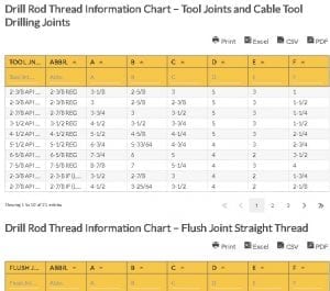
Drill Rod Thread Information Chart – Tool Joints and Cable Tool Drilling Joints
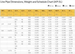
| Tool Jnt Name | Abbr. | A | B | C | D | E | F | |
|---|---|---|---|---|---|---|---|---|
| wdt_ID | Tool Jnt Name | Abbr. | A | B | C | D | E | F |
| 1 | 2-3/8 API REGULAR | 2-3/8 REG | 3-1/8 | 2-5/8 | 3 | 5 | 3 | 1 |
| 2 | 2-3/8 API REGULAR (DSI MOD) | 2-3/8 REG | 3 | 2-5/8 | 2-3/8 | 5 | 3 | 1-1/2 |
| 3 | 2-7/8 API REGULAR | 2-7/8 REG | 3-3/4 | 3 | 3-1/2 | 5 | 3 | 1-1/4 |
| 4 | 3-1/2 API REGULAR | 3-1/2 REG | 4-1/2 | 3-1/2 | 3-3/4 | 5 | 3 | 1-1/2 |
| 5 | 4-1/2 API REGULAR | 4-1/2 REG | 5-1/2 | 4-5/8 | 4-1/4 | 5 | 3 | 2-1/4 |
| 6 | 5-1/2 API REGULAR | 5-1/2 REG | 6-3/4 | 5-33/64 | 4-3/4 | 4 | 3 | 2-3/4 |
| 7 | 6-5/8 API REGULAR | 6-5/8 REG | 7-3/4 | 6 | 5 | 4 | 2 | 3-1/2 |
| 8 | 7-5/8 API REGULAR | 7-5/8 REG | 8-7/8 | 7 | 5-1/4 | 4 | 3 | 4 |
| 9 | 2-3/8 API INTERNAL FLUSH LH, RH | 2-3-8 IF (LH OR RH) | 3-1/2 | 2-7/8 | 3 | 4 | 2 | 1-3/4 |
| 10 | 2-7/8 API INTERNAL FLUSH LH. RH | 2-7/8 IF (LH OR RH) | 4-1/2 | 3-25/64 | 3-1/2 | 4 | 2 | 2-1/8 |
table.wpDataTable { table-layout: fixed !important; }
table.wpDataTable td.numdata { text-align: right !important; }
/* th background color */
.wpdt-c .wpDataTablesWrapper table.wpDataTable thead th,
.wpdt-c .wpDataTablesWrapper table.wpDataTable thead th.sorting {
background-color: #f7c54b !important;
background-image: none !important;
}
/* th border color */
.wpdt-c .wpDataTablesWrapper table.wpDataTable thead th,
.wpdt-c .wpDataTablesWrapper table.wpDataTable thead th.sorting {
border-color: #6b6b6b !important;
}
/* th font color */
.wpdt-c .wpDataTablesWrapper table.wpDataTable thead th {
color: #333333 !important;
}
.wpdt-c .wpDataTablesWrapper table.wpDataTable thead th.sorting:after,
.wpdt-c .wpDataTablesWrapper table.wpDataTable thead th.sorting_asc:after {
border-bottom-color: #333333 !important;
}
.wpdt-c .wpDataTablesWrapper table.wpDataTable thead th.sorting_desc:after {
border-top-color: #333333 !important;
}
/* th active/hover background color */
.wpdt-c .wpDataTablesWrapper table.wpDataTable thead th.sorting_asc,
.wpdt-c .wpDataTablesWrapper table.wpDataTable thead th.sorting_desc,
.wpdt-c .wpDataTablesWrapper table.wpDataTable thead th.sorting:hover {
background-color: #ebebeb !important;
background-image: none !important;
}
.wpdt-c .wpDataTablesWrapper table.wpDataTable thead tr:nth-child(2) th {
overflow: visible;
}
Drill Rod Thread Information Chart – Tool Joints and Cable Tool Drilling Joints
| Tool Jnt Name | Abbr. | A | B | C | D | E | F | |
|---|---|---|---|---|---|---|---|---|
| wdt_ID | Tool Jnt Name | Abbr. | A | B | C | D | E | F |
| 1 | 2-3/8 API REGULAR | 2-3/8 REG | 3-1/8 | 2-5/8 | 3 | 5 | 3 | 1 |
| 2 | 2-3/8 API REGULAR (DSI MOD) | 2-3/8 REG | 3 | 2-5/8 | 2-3/8 | 5 | 3 | 1-1/2 |
| 3 | 2-7/8 API REGULAR | 2-7/8 REG | 3-3/4 | 3 | 3-1/2 | 5 | 3 | 1-1/4 |
| 4 | 3-1/2 API REGULAR | 3-1/2 REG | 4-1/2 | 3-1/2 | 3-3/4 | 5 | 3 | 1-1/2 |
| 5 | 4-1/2 API REGULAR | 4-1/2 REG | 5-1/2 | 4-5/8 | 4-1/4 | 5 | 3 | 2-1/4 |
| 6 | 5-1/2 API REGULAR | 5-1/2 REG | 6-3/4 | 5-33/64 | 4-3/4 | 4 | 3 | 2-3/4 |
| 7 | 6-5/8 API REGULAR | 6-5/8 REG | 7-3/4 | 6 | 5 | 4 | 2 | 3-1/2 |
| 8 | 7-5/8 API REGULAR | 7-5/8 REG | 8-7/8 | 7 | 5-1/4 | 4 | 3 | 4 |
| 9 | 2-3/8 API INTERNAL FLUSH LH, RH | 2-3-8 IF (LH OR RH) | 3-1/2 | 2-7/8 | 3 | 4 | 2 | 1-3/4 |
| 10 | 2-7/8 API INTERNAL FLUSH LH. RH | 2-7/8 IF (LH OR RH) | 4-1/2 | 3-25/64 | 3-1/2 | 4 | 2 | 2-1/8 |
table.wpDataTable { table-layout: fixed !important; }
table.wpDataTable td.numdata { text-align: right !important; }
/* th background color */
.wpdt-c .wpDataTablesWrapper table.wpDataTable thead th,
.wpdt-c .wpDataTablesWrapper table.wpDataTable thead th.sorting {
background-color: #f7c54b !important;
background-image: none !important;
}
/* th border color */
.wpdt-c .wpDataTablesWrapper table.wpDataTable thead th,
.wpdt-c .wpDataTablesWrapper table.wpDataTable thead th.sorting {
border-color: #6b6b6b !important;
}
/* th font color */
.wpdt-c .wpDataTablesWrapper table.wpDataTable thead th {
color: #333333 !important;
}
.wpdt-c .wpDataTablesWrapper table.wpDataTable thead th.sorting:after,
.wpdt-c .wpDataTablesWrapper table.wpDataTable thead th.sorting_asc:after {
border-bottom-color: #333333 !important;
}
.wpdt-c .wpDataTablesWrapper table.wpDataTable thead th.sorting_desc:after {
border-top-color: #333333 !important;
}
/* th active/hover background color */
.wpdt-c .wpDataTablesWrapper table.wpDataTable thead th.sorting_asc,
.wpdt-c .wpDataTablesWrapper table.wpDataTable thead th.sorting_desc,
.wpdt-c .wpDataTablesWrapper table.wpDataTable thead th.sorting:hover {
background-color: #ebebeb !important;
background-image: none !important;
}
.wpdt-c .wpDataTablesWrapper table.wpDataTable thead tr:nth-child(2) th {
overflow: visible;
}
Drill Rod Thread Information Chart – Flush Joint Straight Thread
| Flush Jnt Straight Thread | Abbr. | A | B | C | D | E | F | |
|---|---|---|---|---|---|---|---|---|
| wdt_ID | Flush Jnt Straight Thread | Abbr. | A | B | C | D | E | F |
| 1 | M-50 | M-50 | 2 | 1-3/4 | 1-5/16 | 4 | NO | 1-3/16 |
| 2 | E-ROD | E-ROD | 1-5/16 | 1 | 1-1/2 | 3 | NO | 7/16 |
| 3 | EW – ROD | EW – ROD | 1-3/8 | 1-1/16 | 1-9/16 | 3 | NO | 7/16 |
| 4 | A-ROD | A-ROD | 1-5/8 | 1-17/64 | 1-3/4 | 3 | NO | 9/16 |
| 5 | AW – ROD | AW – ROD | 1-3/4 | 1-3/8 | 1-3/4 | 3 | NO | 5/8 |
| 6 | B-ROD | B-ROD | 1-29/32 | 1-13/32 | 1-7/8 | 3 | NO | 5/8 |
| 7 | BW – ROD | BW – ROD | 2-1/8 | 1-11/16 | 2-1/4 | 3 | NO | 3/4 |
| 8 | N-ROD | 4 THREAD N – ROD | 2-1/8 | 1-7/8 | 2-3/8 | 4 | NO | 1 |
| 9 | N – ROD FAILING TYPE | 3 THREAD N-ROD | 2-3/8 | 1-7/8 | 2-3/4 | 3 | NO | 1-1/8 |
| 10 | NW – ROD | NW – ROD | 2-5/8 | 2-7/32 | 2-3/4 | 3 | NO | 1 -3/8 |
table.wpDataTable { table-layout: fixed !important; }
table.wpDataTable td.numdata { text-align: right !important; }
/* th background color */
.wpdt-c .wpDataTablesWrapper table.wpDataTable thead th,
.wpdt-c .wpDataTablesWrapper table.wpDataTable thead th.sorting {
background-color: #f7c54b !important;
background-image: none !important;
}
/* th border color */
.wpdt-c .wpDataTablesWrapper table.wpDataTable thead th,
.wpdt-c .wpDataTablesWrapper table.wpDataTable thead th.sorting {
border-color: #6b6b6b !important;
}
/* th font color */
.wpdt-c .wpDataTablesWrapper table.wpDataTable thead th {
color: #333333 !important;
}
.wpdt-c .wpDataTablesWrapper table.wpDataTable thead th.sorting:after,
.wpdt-c .wpDataTablesWrapper table.wpDataTable thead th.sorting_asc:after {
border-bottom-color: #333333 !important;
}
.wpdt-c .wpDataTablesWrapper table.wpDataTable thead th.sorting_desc:after {
border-top-color: #333333 !important;
}
/* th active/hover background color */
.wpdt-c .wpDataTablesWrapper table.wpDataTable thead th.sorting_asc,
.wpdt-c .wpDataTablesWrapper table.wpDataTable thead th.sorting_desc,
.wpdt-c .wpDataTablesWrapper table.wpDataTable thead th.sorting:hover {
background-color: #ebebeb !important;
background-image: none !important;
}
.wpdt-c .wpDataTablesWrapper table.wpDataTable thead tr:nth-child(2) th {
overflow: visible;
}
Drill rod thread comes in various forms and sizes, where some are categorized under the American Petroleum Institute (API) connections and others as premium connections.
API Connections
Single shoulder connections are possible with these, where there is only one torque shoulder on both box and pin. These can be identified as:
- Regular
- Internal Flush (IF)
- Full Hole (FH)
- Numeric Connection (NC)
Premium Connections
Premium connections generally have a double shoulder. They possess an extra torque shoulder at the end of the box, and in the nose of the pin. They can handle higher torque applications and are available in various shapes and sizes:
- Grant Prideco (XT)
- Tenaris (DSTJ)
- Vam (Vam Eis)
- DP Master (MT)
Drill Rod Thread Compatibility Chart Abbreviations:
- A – Outside Diameter
- B – Major Thread Diameter
- C – Length of Pin
- D – Threads per inch
- E – Taper per Foot
- F – Tool Joint Bore
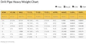
Go here if you are looking for the Drill Pipe Heavy Weight Chart.
The Oilfield Equipment related post Drill Rod Thread Compatibility Chart is from Flowtech Energy. Looking for Oilfield Equipment including New, Used, Remanufactured and Surplus Oilfield Supply, check out our inventory or call our toll free number at 877-645-6693 for more information.
From https://www.flowtechenergy.com/charts/drill-rod-thread-compatibility-chart/